Geiger Electronic Circuit !
The circuit below rapresents the electronic of a Geiger Counter. As you can see the UPPER SECTION (GREEN) of the circuit is a voltage regulator, while the BOTTOM SECTION (ORANGE) rapresents a pulses counter.
The main component used in the circuit above is the IC 555 CMOS, where its output change continuely through the use of the component Q1. The Q1 output is applyed to a power transistor with at least 400 V Vce. This transistor open and close the power supply to the Transformer T1.
Cause is very difficult to have the right Transformer T1, the better way is to build one by yourself. These kind of operation is not hard to do, but require a lot of care. In order to do that you must use a 25 X 25 ferrite core in size. The primary must have 50 coils with a 0.1 mm in diameter wire. The secondary, on the other side, must have 500 coils with the same wire dimension as the above one. In order to avoid electrical discharge it's necessary that the input and output wire are not too close.
The second 555 is used as pulses counter. As you can see the circuit uses it as a monostable system. Every time the monostable is triggered, its output Q, send a positive pulse whose lenght is established by R4, R5, R6 values.
The output Q of the integrated U1, is sent to a piezoelectric loudspeaker, that emits a sound every pulse recorded by the counter. Also an micro-ammeter is used in order to measure an average corrent proportianal to the pulses counted by the counter, through the use of R7 and C4. The ammeter must have a 50 - 500 micro-amperes as a full range scale.
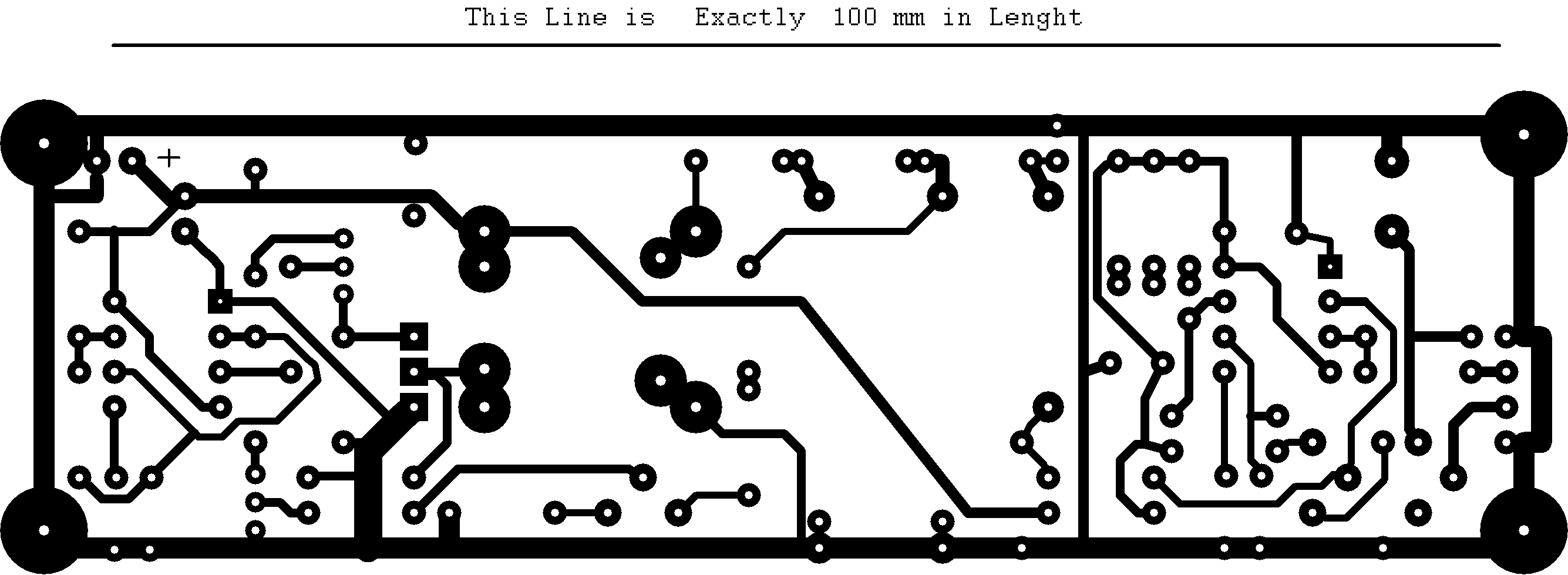
Printed
Circuit !
The components view is:
All the resistor are 1/8 W, the condensers are at least 100 V, the electrolityc condensers are 25 V. The power supply is 12 V.


